Evaluation_Formulae3
3.2.4.2 Evaluation Formulae
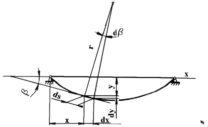
Considering the fact that the violin body deformations are comparatively small we can derive the deflection line according to Fig. 3–44 where the following is valid:
 ,(3.62)
where y – deflection in xpoint,
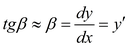
b – angle of bend (turn) in x point.The angle of the violin body deflection we calculate according to the formula presented in paper (Skalmiersky, 1981):
 ,(3.63)
where P = k2 EJ.
In the particular case for the values J = 35 cm4, F = 200 N, E = 1,5. 106 Pa, a = 16 cm, a = 15 ° , h = 2 cm, l = 35,5 cm, k = 0,001918 cm-1, the deflection angle is equal to 0.0005357 rad = 0,0308 °. The deflection angle is minimal as seen from the calculated values.
We calculate the maximal deflection in point x = a from the formula (Skalmiersky, 1981):
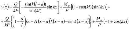 (3.64)
where Q = 2. F. sin α, P = F. cos α,
Mo = h. F. cos α,
H(a) – function of Heaviside a.
After substitution of the actual numeric data is y (16 cm) = 0, 026 cm.
For the needs of the analysis of the reconstructed image of the violin body, the images were recorded from two positions in y axis direction, i.e. in the bridge action direction. For evaluation the FC method was used (see chapter 3.1.5.2).
During the analysis of holographic interferogram of the violin body deflection only the displacements in the directions of y axis (in the direction of bridge action) were considered and compared with the calculated deflection line.
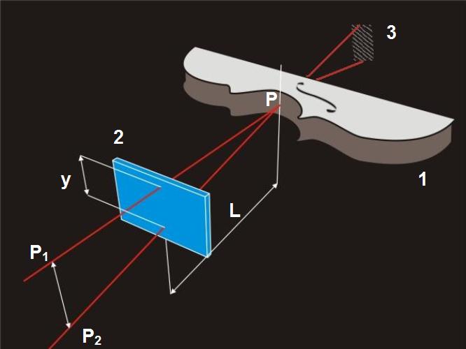
1 – image, 2 – hologram, 3 – interference order


