Description_of_the_Experiment1
3.2.2.2 Description of the Experiment
For the experimental research of tension-deformation state in the cutting zone, orthogonal cutting was used. Deformations originated by penetration of the cutting wedge into the spruce and beech wood during the beginning stage corresponded to the uniaxial loading by pressure forces. That is why we carried out an experiment aimed at recording, reconstruction and analysis of holographic interferograms obtained by the double-exposure method. The first exposure was carried out by superposition of the object wave reflected from the investigated object before deformation and the reference wave, while the second exposure was made after deformation of the object. The double-exposure holographic interferogram thus obtained represents the state of the investigated object at the moment of the second exposure. This method, however, does not offer the time behaviour of the investigated object deformation (Aleksandrov, Bonč–Brujevič, 1967).
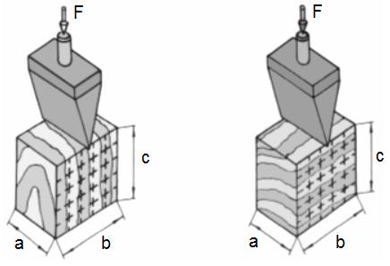
Fig. 3–28 Action of the cutting wedge (a = 44 mm, b = 59 mm, c = 72 mm)
a) in longitudinal direction
b) in tangential direction
To display the interaction of the cutting wedges with the test specimens the holographic system was created as shown in the optical chart in Fig. 3–29.
The narrow laser beam was divided in two by the beam splitter (2). The beam that passed through the beam splitter was reflected from the mirror (32) and directed to the objective (42) where it was expanded and then fell on the holographic plate (7). This beam represents the reference branche. The second beam created by the reflex from the interface of the beam splitter (2), falls on the mirror (31), is oriented to the objective (41) where it is expanded to the object. The light is diffusively reflected from both the cutting wedge and the test specimen surfaces and falls on the holographic plate (7).
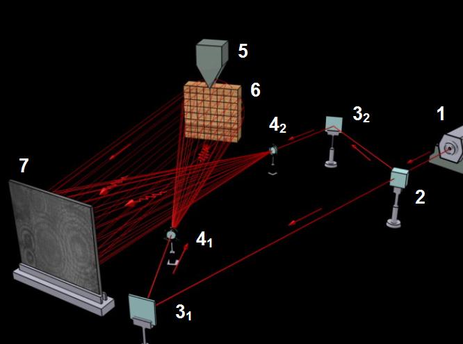
1 – laser, 2 – beam splitter, 31, 32 – mirrors, 41, 42 – objectives, 5 – cutting wedge, 6 – test specimen, 7 – hologram
The reconstructed image was recorded into the CCD camera from two different directions determined by the positions of the main point of the objective. The real set-up used during the reconstruction is displayed by the chart in Fig. 3–30 where Ai is the i-th investigated point on the object surface, V1 and V2 are intersections of the connecting lines between the individual positions of the camera objective main point and point Ai of the object with hologram.
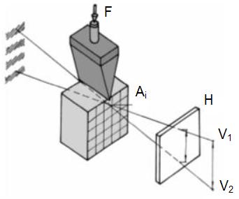
F – loading force, V1, V2 – positions of the main points of the objective, H – hologram,
Ai – investigated point of the object surface


