Holografia a jej technické aplikácie
3.3.1 Holographic Set-Ups for Transparent Objects
Similarly to those for diffusively reflecting objects there are two basic optical set-up arangements:
- Method by amplitude splitting (Fig. 3–55, Fig. 3–56)
- Method by wavefront splitting (Fig. 3–57)
The method by amplitude splitting (Fig. 3–55) is specific by expanding a narrow laser beam and transforming it into a planar light wave before the beam splitter due to which only one three-dimensional filter with a micro-objective is needed.
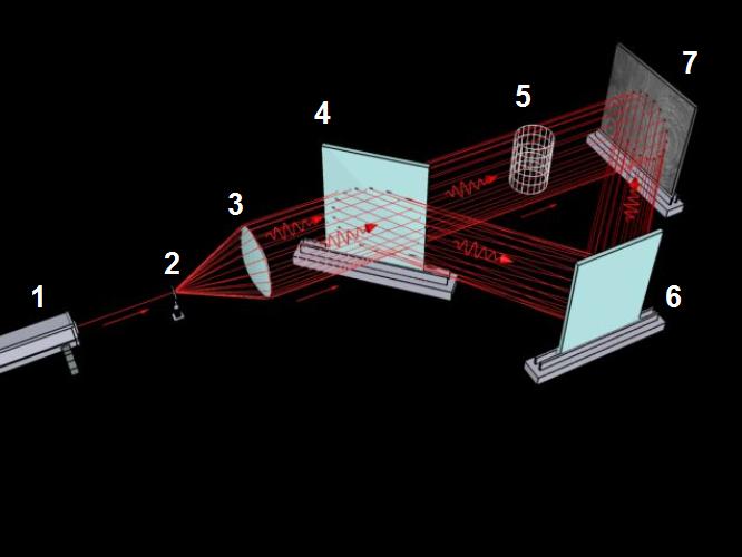
(beam is expanded before splitting)
1 – laser, 2 – micro-objectiv, 3– objectiv, 4 – beam splitter, 5 – phase object, 6 – mirror, 7 – holographic plate
The disadvantage of this method lies in the need for a beam splitter of large dimensions and in troubles with the contrast of interference fringes.
Method by amplitude splitting (Fig. 3–56) is characterised by using the beam splitter with small dimensions unlike the previous method, and easier adjustment of the contrast on the holographic plate.
The optical set-ups assembled according to the methods by amplitude splitting use the laser radiation light flow more efficiently, which allows shortening of the exposure time, and are more universal. The methods by wavefront splitting are more simple and need less optical components (Fig. 3–57).
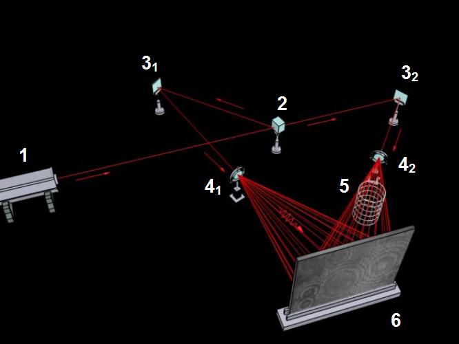
(beam is expanded after splitting)
1 – laser, 2 – beam splitter, 31, 32 – mirrors, 41, 42 – lenses, 5 – phase object, 6 – holographic plate
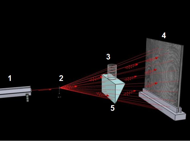
1 – laser, 2 – objective, 3 – phase object, 4 – holographic plate, 5 – optical wedge
For the study of
two-dimensional or rotation-symmetric transparent inhomogeneous
substances various types of interferometers
(see Fig. 3–58, Fig. 3–59, Fig. 3–60) are
possible to apply. The principle consists in interference of
reference beam r whose wavefront is usually planar, with
object beam p whose wavefront is deformed during its
transmission through the measured object of length L. Both
paths must be of the same length. In Fig. 3–58 the
Jamin interferometer is presented that is relatively simple
but its comparatively small viewing field is limited by the size of
beam splitters (2). Moreover, the distance between the object and
reference beams is too small, which can cause troubles where the
reference beam is influenced by the measured phase object
(Pavelek, Štětina,
1997).
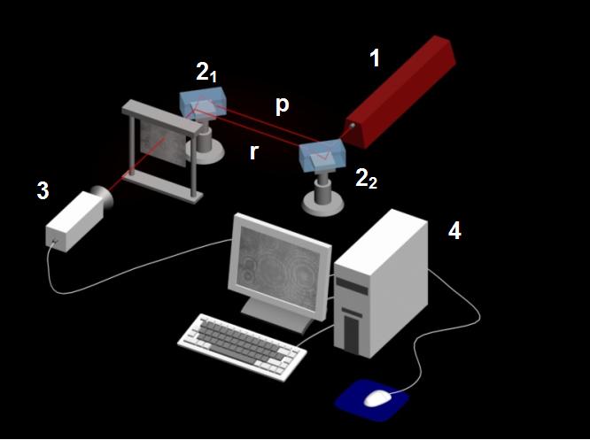
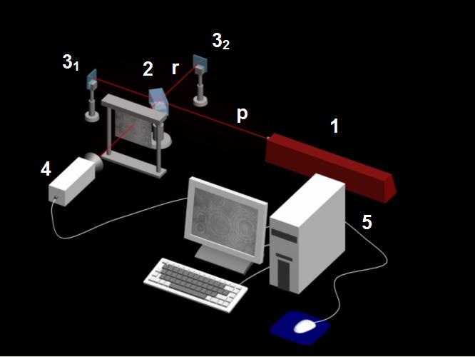
1 – laser, 21, 22 – beam splitter, p – object beam, r – reference beam, 3 – CCD camera, 4 – computer
During the research of transparent as well as diffusively reflecting objects we can more frequently meet with the Michelson interferometer (Fig. 3–59), that is more sensitive than the previous one. Its higher sensitivity is reached because object beam p passes through the measuring space twice. The limitation of this set-up is in lower accuracy of the measured values since in consequence of the light trajectory curvatures several beams propagate there and back through different places of the transparent object (Pavelek, Štětina, 1997).
(beam is expanded before splitting)
1 – laser, 2 – beam splitter, p – object beam, r – reference beam, 31, 32 – mirror, 4 – CCD camera, 5 – computer
The chart of Mach–Zehneder interferometer is displayed in Fig. 3–60. The narrow light beam generated by laser (1) is divided by beam splitter (21) into the object p and reference r beams. They are directed by mirrors (3) to the place with beam splitter (22) that connects the object and reference beams – they interfere.
Besides the above mentioned interferometers, during the research of transparent objects we can meet with other types of interferometers, for example Shearing interferometer suitable for investigation of refractive index derivations in selected direction, Fabry-Perot interferometer characterised by several times higher sensitivity than the other mentioned types (Pavelek, Štětina, 1997).
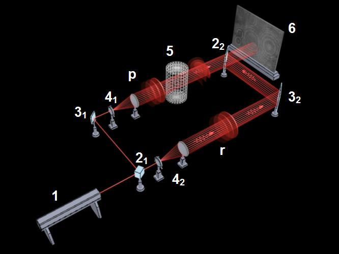
1 – laser, 21, 22 – beam splitters, 31, 32 – mirrors, 41, 42 – objective, 5 – transparent body, 6 – hologram, p – object beam, r – reference beam


