Fringe_Formation_in_Holographic_Interferometry
3.1.4 Fringe Formation in Holographic Interferometry
Specialists investigate interference fringes from many different viewpoints – not only their densities, widths but mainly their shapes that sometimes take such forms that seem to be almost fantastic to laymen. They look very decorative. But much more important than the aesthetic impression is the information encoded in them. It is usually not easy to decrypt (Sedláček, 1982).
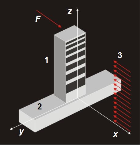
Let us analyse the simple case where the displacement occurs only in one direction. The subject of investigation is a console support with one end firmly anchored. This support is illuminated by the plane wave propagating in the direction of –z axis perpendicular to its surface. The laser radiation scattered on the support is recorded on the hologram. Then the free end of the support is slightly shifted by force F in the direction of –z axis and we make the second exposure.
![]()
(shifting from the force F in the direction of +z axis, illumination in the direction of –z axis),
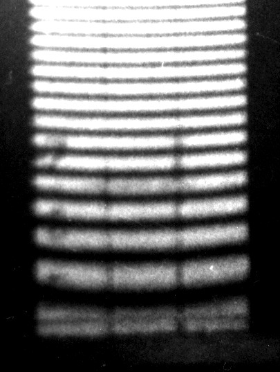
b) Interferogram of diffraction of the console support (Tanner, 1968)
c) Expanded part of the interferogram
1 – support, 2 – basic plate, 3 – plane light wave, F – force, x, y, z – coordinate axes
In Fig. 3–8 b is the photography of the double-exposure holographic interferogram of the console support obtained by the double-exposure method. Because the displacements are small each point of the support is displaced only in the direction of z axis. In the initial state all points are situated in the plane z = 0. After shifting each point is displaced into the position described by function f = Z(x).
Before deformation, the light wave travels the distance l0 from the source to the point of the object and then back to the observer (or camera) and after deformation of the object the light wave travels the distance l0 – 2Z(x).
The corresponding phase change is then equal to:
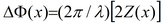 ,
(3.19)
,
(3.19)
where λ is the wavelength of laser radiation.
Let us notice that we still have not mentioned the hologram: its function consisted mainly in recording of the two wavefronts and then their simultaneous reconstructing, i.e. obtaining the interferogram displayed in Fig. 3–8 b.
Now we assign the interference orders to the bright fringes on the interferogram. As the skeleton of the support is not displaced the bright fringe is given the number n = 0. To the following bright fringes we assign successive numbers n = 1, 2, 3 … the phase change corresponds to the fringe with the number n (3.19).
After modification we get the following formula for calculation of the displacement:
 , (3.20)


