Derivation_of_the_Fundamental_Equation_of_H._I.
3.1.4.1 Derivation of the Fundamental Equation of Holographic Interferometry
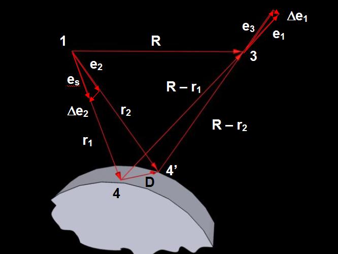
The role of the hologram consists in reproducing laser radiation dispersed by the object before and after deformation. The size and position of the hologram represent the limits within which the object is visible. The corresponding components of the physical system are displayed in Fig. 3–9 a. The object is illuminated by the point source located in point (1). The light scattered by object point (4) passes through the hologram into view point (3). The double-exposure hologram is recorded and the displacement of point (4) to point (4’) is determined by displacement vector D. In Fig. 3–9 b several vectors used for determination of the relation between the phase difference of the interfering beams d and displacement vector D are demonstrated.

a) Chart for derivation of the fundamental holographic interferometry relation
b) Point position vectors and wave vectors
1 – point illumination source, 2 – observer, 3 – view point, 4 – point on the body surface, 5 – the object before deformation, 5’ – the object after deformation, 6 – hologram,
D – displacement vector, r1, r2 a R – vectors of points 4, 4’ and 3,
es, e1 a e2, e3 – unit vectors of illumination and observation of points 4 and 4’
Vectors R and r1 are set in the plane determined by points 143 and es, e1 represent the unit vectors of illumination and observation. Difference D of optical paths of the beams from illumination source (1) through mutually equivalent points (4) and (4’) to view point (3) can be expressed by relation (Aleksandrov, Bonč-Brujevič, 1967):
 .(3.21)
The phase difference
between the interfering beams d
is connected with optical difference of beam travelling D
that can be expressed through the wave number :
:
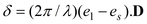 ,(3.22)
where l is the wavelength of light.
Equation (3.22) can be expressed by the following form:
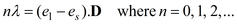 (3.23)
where n is the absolute interference order of the bright interference fringe in the investigated point of the body surface.
The equation (3.23) determines the relation between the displacement vector of the investigated point of the body surface, parameters of the interferometer optical chart (expressed by the illumination and viewing directions) and the order of interference fringe n at this point on the interferogram. It is called the fundamental equation of holographic interferometry.
For analysis of holographic interferograms it is necessary to introduce the term of sensitivity vector (Ennos, 1968):
 .(3.24)
By substituting the sensitivity vector to the fundamental interferometric equation we obtain:
 .(3.25)
The physical meaning of (3.25) can be determined from the analysis of the illumination chart and observation of any surface point of the body (1) visible in Fig. 3–10.
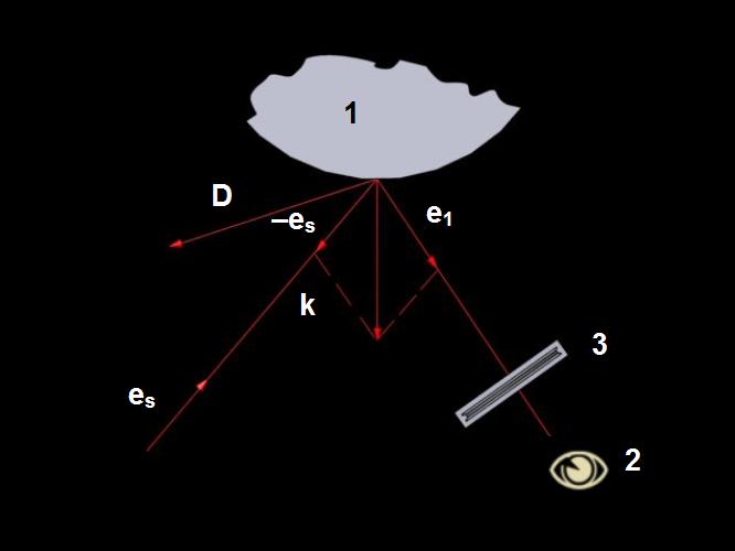
es, e1 – unit vectors of illumination and observation, 1 – point on the object surface, D – displacement vector, k – sensitivity vector, 2 – observer, 3 – hologram
The direction of the point illumination (1) is determined by unit vector es and the direction of the observation through the hologram by unit vector e1. We assume that displacement vector D of the investigated point is set in the plane determined by unit vectors es and e1. From the above chart it follows that the sensitivity vector is oriented along with the symmetry axis of the angle formed by the illumination and viewing directions.
This way, the interference fringe pattern at the fixed view point position enables us to determine the projection of the displacement vector to the sensitivity vector, i. e. generally, the deformations of the body (the interference fringes are not directly interpretable), by equation (3.25).
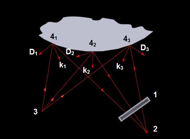
These circumstances fundamentally obstruct the quantitative analysis of the holographic interferograms of diffusively reflecting bodies. The shape of interference fringes is influenced by changes on the body surface, such as values and directions of both the sensitivity and displacement vectors. These ratios are schematically displayed in Fig. 3–11. The sensitivity vectors k1, k2, k3 have different directions and values for some points of the surface 41, 42, 43, illuminated by point source (3) and observed from point (2). Displacement vectors at these points D1, D2 and D3 have also various directions and values. The use of collimated illumination makes it possible to ensure the same direction and values on the whole investigated surface.